Many process engineers treat pressure drop as a static spec sheet number. It isn't. It's a dynamic signal that shifts with velocity, fouling, and liquid loading — and misreading it leads to flooding, carryover, or premature mesh failure.
This article breaks down what pressure drop actually represents, the ranges you should expect, what drives it, how it's measured, and what happens when it drifts outside recommended limits.
Key Takeaways
- Clean, dry demister pads typically run under 1 inch of water column at design velocity
- Pressure drop results from mesh density, wire diameter, and gas velocity, not a setpoint you choose
- Rising pressure drop usually signals fouling, flooding, or mesh wear, not higher throughput alone
- Wire diameter, void volume, and pad thickness trade off pressure drop against droplet-capture efficiency
- Gemini Wiremesh density control (near-0% to 98%+ void volume) lets buyers tune this trade-off per duty
What Pressure Drop Represents in Wire Mesh Mist Eliminators
Pressure drop is the pressure loss (usually measured in inches or millimeters of water column) that a gas stream experiences crossing a knitted mesh pad. It's the resistance the mesh creates as gas is forced through millions of tiny openings between wire filaments.
Pressure drop is both a design output and an operating variable:
- At the design stage, mesh density, wire diameter, and pad thickness set a baseline resistance before the pad ever sees process gas
- In operation, plant teams monitor it continuously as a health check for fouling, flooding, or degradation
That dual nature trips people up. A number on a datasheet describes clean conditions in a lab. The number on your control room screen describes a pad that's been running for months, possibly loaded with liquid or partially fouled. Both matter, but they're not interchangeable.
Pressure drop is not something you dial in. It's a derived characteristic: the consequence of mesh geometry meeting real gas flow. Change the void volume, wire diameter, or velocity, and pressure drop changes with it.
Factors That Influence Pressure Drop in Real-World Operation
Theoretical clean-pad values from a vendor datasheet rarely match what a differential pressure gauge shows six months into operation. Several factors explain the gap.
Design constraints set the baseline:
- Mesh void volume typically runs 97-99% in knitted wire mesh mist eliminators: high open area keeps clean-pad resistance low
- Wire diameter and pad thickness both add resistance as they increase
- Knitting tolerances can uneven pore distribution across the pad face and create localized high-resistance zones
Operating conditions add variability:
- Gas velocity fluctuates with process load, and pressure drop rises non-linearly as velocity increases
- Liquid loading changes dynamically: a liquid slug temporarily raises resistance well above dry-pad values
- Gas density and composition shift the pressure-drop curve even when face velocity stays constant
Environmental and time-based effects compound the problem:
- Fouling from solids, polymer buildup, or corrosion products narrows the free flow area
- Mesh compression, filament fatigue, or partial collapse over years of service gradually pushes pressure drop upward
- Vibration or thermal cycling can shift pad seating, open bypass gaps, and raise effective velocity through the remaining mesh

A pad that reads 0.5 inches of water column at commissioning and 1.5 inches three years later hasn't changed its design. Something in the operating environment has.
Range of Pressure Drop
Pressure drop range is governed by two things: the mesh geometry itself, and the conditions you're running it under.
Nominal Operating Range
For clean, dry pads at design velocity, published manufacturer data puts pressure drop usually under 1 inch of water column. That figure assumes:
- A clean pad with no fouling or liquid accumulation
- Gas velocity within Souders-Brown design limits (a common K-value is 0.35 ft/s)
- No significant liquid loading beyond normal entrainment
Reduce that K-value for dirty liquids, high viscosity, or lower surface tension. In wet service, the range shifts upward: one sulfuric acid case reported 0.70–0.98 inches of water column across two-stage wire-mesh pads at 15–18 ft/s, still workable but clearly above clean, dry baselines.
Allowable Tolerance and Boundary Limits
There isn't a single universal flooding pressure drop number published across the industry. Once liquid accumulates in the mesh past its holding capacity, pressure drop rises sharply rather than gradually. That inflection point, not a fixed pressure number, is the practical warning sign.
Short-term spikes from process upsets or liquid slugs are often self-correcting and rarely signal a design problem. Continuous elevated readings that never settle usually point to fouling or sustained overloading.
Safe Operating Margin
Designers rarely spec a pad to run right at its flooding velocity. Margin below that threshold covers normal process variability: compressor recycle, startup transients, or a feed slightly dirtier than the design basis.
AMACS notes that typical knitted wire-mesh mist eliminators handle liquid loads up to roughly 1 US gal/min/ft² before performance degrades. That figure is a practical benchmark when you size the operating margin.

Key Technical Properties Governing Pressure Drop
Pressure drop isn't controlled by one variable. It's the product of mesh construction interacting with process conditions.
Stability and Variability
Pressure drop doesn't rise in a straight line with velocity. It curves upward, so small velocity increases near the top of the operating range cause disproportionately large pressure drop jumps.
Separately, pressure drop drifts upward over the pad's service life as fouling and wear accumulate, even at constant velocity.
Mesh Density and Void Volume
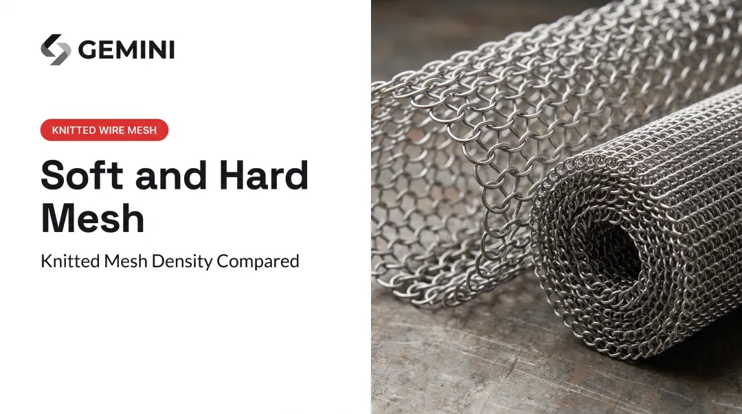
Void fraction and packing density directly trade off against each other. As void fraction and wire diameter decrease, wet pressure drop rises. Higher packing density and specific surface area push pressure drop up as well.
In short: denser mesh catches more droplets but costs more energy to push gas through. Looser mesh saves energy but lets finer droplets slip past.
Wire Diameter and Pad Thickness Coupling
Finer wire diameters increase surface area per unit volume, which improves droplet capture, but that same surface area raises resistance. Thicker pads follow the same logic: more material in the gas path means better efficiency and higher pressure drop.
This creates a real specification tension:
- Energy-sensitive systems (compressor suction scrubbers, high-throughput gas processing) often need the lowest achievable pressure drop
- Fine mist capture applications (pharmaceutical off-gas, corrosive acid mist) often need higher-density mesh regardless of the pressure drop cost
Gemini Wiremesh's density control spans near-0% to over 98% void volume, with up to 300% stretching capacity during fabrication. That range gives buyers a wider window to hit the right point in the trade-off instead of accepting a fixed off-the-shelf compromise.

How Pressure Drop Is Specified, Measured, and Validated
Pressure drop functions as both a spec you check before ordering and a signal you monitor for the life of the pad.
Specification and Documentation
Vendor datasheets typically list clean, dry pressure drop at a rated velocity. That number describes a controlled lab condition: clean air, no liquid loading, and uniform flow distribution. It is not the number you should expect on day 400 of operation.
Measurement and Verification Methods
In the field, differential pressure transmitters or manometers installed upstream and downstream of the pad are the standard tools. A few things affect measurement accuracy:
- Place pressure taps far enough from the pad face to avoid localized turbulence
- Treat single-point readings cautiously when flow is maldistributed across the face
- Expect clean lab air/water tests to read lower than fouled or uneven field service
Published experimental work on knitted mesh pads often used a U-tube manometer and reported the height difference as inches of water column (in. WC). That approach still matches what many U.S. field installations use today.
To validate a pad against its datasheet, compare clean-condition field readings at the rated velocity with the published curve. Sustained deviation beyond the expected wet operating range usually points to fouling, flooding, or installation issues—not a bad factory number.

Implications of Operating Outside the Recommended Pressure Drop Range
High pressure drop is usually a symptom of a deeper process problem, not only an energy cost.
Performance loss mechanisms:
- Reduced separation efficiency as gas channels around saturated sections of mesh instead of through it
- Liquid carryover downstream into compressors, exchangers, or other sensitive equipment
Accelerated wear or failure:
- Sustained high differential pressure can compress the mesh structure over time
- Structural fatigue in the wire filaments can lead to partial collapse, which drives pressure drop even higher
Broader consequences:
- Exceeding a vessel's design pressure drop rating can violate its mechanical design basis
- Carryover that exceeds permit limits creates compliance exposure
- Chronic overloading can void manufacturer warranty terms tied to specified operating envelopes
Common Misinterpretations in Practice
A few recurring mistakes show up across plants:
- Treating the clean-pad number as fixed. It's a starting reference point, not a permanent operating constant.
- Reading pressure drop in isolation. Liquid loading and velocity interact. A moderate velocity rise with high liquid loading can push the pad into flooding faster than either factor alone.
- Applying lab curves directly to field data. Lab tests don't account for fouling, corrosion buildup, or flow maldistribution that field installations experience daily.
Frequently Asked Questions
What is an acceptable pressure drop in a heat exchanger?
Acceptable pressure drop in a heat exchanger depends on duty, fluid properties, and operating conditions—there is no single fixed limit. Demister pads, by comparison, are generally kept well below 1 inch of water column when clean.
How is pressure drop calculated?
Pressure drop across a demister pad is calculated using empirical correlations tied to gas velocity, mesh void fraction, packing density, and wire diameter. These correlations are typically validated against vendor or lab test data, with reported accuracy in the range of ±15-20%.
What causes high pressure drop in demister pads?
The main causes are fouling from solids or polymer buildup, flooding from excessive liquid loading, gas velocity above the design range, and mesh degradation from age or corrosion. Any of these narrows the effective flow path through the mesh.
How thick should a demister pad be?
Knitted mesh pads are usually 4-6 inches thick, though some applications use thicker configurations up to 10 inches for higher efficiency needs. Thicker pads improve droplet capture but increase pressure drop, so thickness should match the separation duty.
What is flooding in a mist eliminator?
Flooding occurs when the mesh becomes saturated with liquid faster than it can drain, causing pressure drop to rise sharply and liquid to carry over downstream. It's typically first noticed as an unexplained pressure drop spike or visible liquid carryover.
Does mesh density affect pressure drop?
Yes. Higher density (lower void volume) mesh raises pressure drop while improving droplet capture. Gemini Wiremesh offers density control from near 0% to over 98% void volume, so you can tune that balance for your application.